Pulsiv OSMIUM Microcontrollers
Pulsiv OSMIUM Microcontrollers
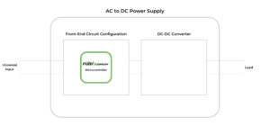
Our new method of efficiently converting AC to DC is achieved by using a Pulsiv OSMIUM microcontroller to monitor real-time grid condition, manage power factor correction (PFC) and regulate a high-voltage DC output to support a wide range of compatible DC-DC converters. It maintains a flat efficiency profile over the full load range and complies with strict EMC/THD regulations. Quality, reliability, performance and availability have been addressed by combining our unique intellectual property with industry standard devices from carefully selected global tier 1 chip manufacturers.
| Series | Output Power Range |
Active Bridge (Optional) |
X-Cap Discharge (Optional) |
Hold Up (Optional) |
Grid Failure Detection |
Selectable HVDC Output |
Power Consumption Indicator |
Package | Operating Temp °C |
Reel Size | Datasheet |
|---|---|---|---|---|---|---|---|---|---|---|---|
| PSV-AD-150 | 1W – 150W | QFN24 | -40 to +85 | 250/3000 | Open | ||||||
| PSV-AD-250 | 1W – 250W | ||||||||||
| PSV-AD-10K | 1W – 10kW | Currently Under Development | |||||||||
Microcontroller Features
Active Bridge Control
Active bridge signals are provided by the Pulsiv OSMIUM microcontroller to drive a high-side low-side MOSFET configuration that increases overall efficiency by up to 1.4% (90VAC line input). This feature is particularly useful at higher power levels and requires only two MOSFET’s (see datasheet). A full active bridge can be implemented with very few additional components. (Please contact Pulsiv for details).
X-Cap Discharge
When the grid supply fails, the Pulsiv OSMIUM microcontroller will produce the signals to discharge the x-capacitor automatically using low cost switches in the half active bridge. This replaces alternative and more expensive methods such as using resistors or an additional external silicon chip. When a half active bridge isn’t fitted, an alternative circuit can be used.
Hold Up
For applications that require hold up, an optional circuit can be used to activate a Thyristor below a certain voltage threshold (determined by a simple resistor network) and maintain the HVDC output using hardware rather than software.
Grid Failure Detection
A warning signal is provided when the grid supply falls below 50V to give downstream systems the maximum time to take action. This is particularly useful in safety critical applications or where a controlled shut down is required.
Selectable Max HVDC Output
Providing the ability to select the voltage rating of the storage capacitor, allows engineers to optimise the capacitor selection for cost or performance. This flexibility enables engineers to configure the design according to the needs of their application by choosing between 160V or 200V capacitors.
Power Consumption Indicator
The POWER_USED pin displays real-time consumption by toggling at a fixed rate that is directly proportional to the actual delivered power. Our method does not require expensive current measurement techniques, but performs a calculation during each grid cycle.
AUX Output Control
The SECONDARY_PWM output can be used to drive an auxiliary supply for systems that need power when the DC-DC converter is switched off. Please contact Pulsiv for details as the supporting components will depend on specific power requirements.
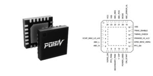
Pulsiv OSMIUM Microcontroller
Microcontroller Stocking Distributors

AC to DC Front-End Circuit Configurations
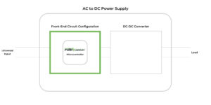
All Pulsiv OSMIUM microcontrollers are combined with commodity system components to produce AC to DC front-end circuit configurations which support a variety of different features and power levels. Once a circuit configuration has been chosen, development engineers can integrate a suitable DC to DC converter to produce a complete power supply design.
| Options |
|
|||||||||||||||||||||||||||||||||||||||||||||
|---|---|---|---|---|---|---|---|---|---|---|---|---|---|---|---|---|---|---|---|---|---|---|---|---|---|---|---|---|---|---|---|---|---|---|---|---|---|---|---|---|---|---|---|---|---|---|
| Configuration Number |
Output Power Range |
Basic Configuration |
Hold Up | Half Active Bridge |
X-Cap Discharge |
|||||||||||||||||||||||||||||||||||||||||
| PSV-CCAD-150 | 1W – 150W | |||||||||||||||||||||||||||||||||||||||||||||
| PSV-CCAD-150H | ||||||||||||||||||||||||||||||||||||||||||||||
| PSV-CCAD-250 | 1W – 250W | |||||||||||||||||||||||||||||||||||||||||||||
| PSV-CCAD-250H | ||||||||||||||||||||||||||||||||||||||||||||||
| PSV-CCAD-250X | ||||||||||||||||||||||||||||||||||||||||||||||
| PSV-CCAD-250A | ||||||||||||||||||||||||||||||||||||||||||||||
| PSV-CCAD-250HX | ||||||||||||||||||||||||||||||||||||||||||||||
| PSV-CCAD-250AH | ||||||||||||||||||||||||||||||||||||||||||||||
| TBC | 1W – 10kW | Currently Under Development | ||||||||||||||||||||||||||||||||||||||||||||
*Design Calculator
The design calculator can be used to determine the required values of the Inductor (Lch), Resistor (Rch) & Capacitor (Cch) which differ depending on the power level.
Additional Design Resources
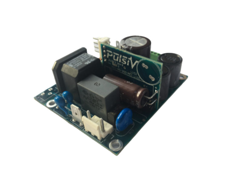
AC to DC Front-End Evaluation Boards
The Pulsiv OSMIUM AC to DC front-end evaluation board allows engineers to quickly evaluate our new power conversion technology for any application up to 250W. It supports universal input and can be adapted to test various circuit configurations. Simply connect a suitable DC-DC converter on the HVDC output to produce a complete power supply prototype.
Full AC to DC Power Supply Evaluation Boards
We are currently developing a range of full AC to DC power supply evaluation boards to demonstrate our technology in a complete end-to-end solution which includes an AC to DC front-end circuit configuration and a carefully selected DC-DC converter.

Reference Designs
Reference designs deliver a complete end-to-end solution that combine a Pulsiv OSMIUM microcontroller, AC to DC front-end circuit configuration and a carefully selected DC-DC converter. Developed for both general purpose and specific applications, they can be adopted without making any changes or further modified according to the needs of the end product.
Pulsiv OSMIUM reference designs are offered in two formats. A paper reference design provides a proven foundation for customers to adapt according to cost, size or performance requirements and suitable for general purpose applications. A full reference design additionally includes a complete PCB layout with EMI test data.

Video Tutorials
Our tutorial videos have been created for engineers who are developing power electronics designs based on Pulsiv OSMIUM technology. They provide an overview to various topics and compliment supporting documentation.

Direct Technical Support
The Pulsiv team and distribution network are ready to support customers who wish to use Pulsiv OSMIUM technology in their application. Our aim is to simplify the design process and ensure maximum performance is achieved in the end application.
If you need technical support with our technology or how to configure it for your application, please contact us directly. We are ready to support all questions via telephone, video call or on-site visit.